A journey of discovery from typing a URL in a browser to displaying a web page
Preface
Understanding the whole picture of networking is still necessary for those who work with networking technology on a regular basis. I recently read “How the Web is Connected” to record my reading notes.
Now let’s start the journey of discovery from typing a URL into a browser to the display of a web page!
1 Browser Generated Messages
1.1 Resolving URIs
After the user enters the URL in the browser, the first step of the browser is to parse the URI.
For example, by splitting and parsing https://www.wxample.com/dir1/file1.html, you will know that you want to access www.example.com, a file with path /dir1/file1.html on the web server.
1.2 Generating HTTP request messages
After determining the web server and file name, the browser generates the HTTP request message based on this information.
The http protocol defines the content of the messages and the steps involved in the interaction between the client and the server. According to the http protocol, the request message and response message look like this: 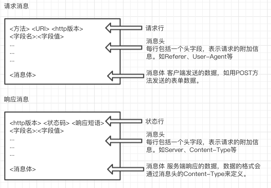
1.3 Querying a DNS server for the IP address of a Web server
After generating the HTTP message, the browser also needs to look up the IP address based on the domain name in order to delegate the message to the operating system.
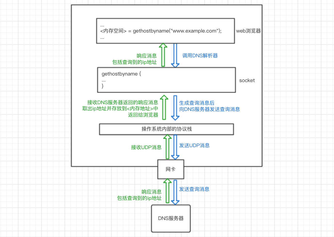
Our computer’s operating system has a DNS resolver in its socket library (a socket library is a collection of program components used to call network functions). After the resolver is called in the browser program, it is delegated to the operating system’s protocol stack to perform the operation of sending the message, which is then sent to the DNS server via the network card. The DNS server then returns a response message containing the queried IP address. The resolver takes the IP address and writes it to the memory address specified by the browser. As shown below:
So how does a DNS server look up an ip address?
All information in DNS servers is stored in a hierarchical structure according to the domain name, with the top level being the root domain. For example, to query the ip address corresponding to www.example.com, the client will first access the nearest DNS server, which will look for records matching the queried domain name in the saved records, and if there are any, it will be returned to the client. If it does not, the lookup starts from the root domain and works down. If there is no domain name www.example.com in the root DNS server, and you know that it belongs to the com domain according to the domain name structure, the ip address of the DNS server in the com domain will be returned, and so on, and finally the ip address of www.example.com will be returned.
1.4 Delegating messages to the stack
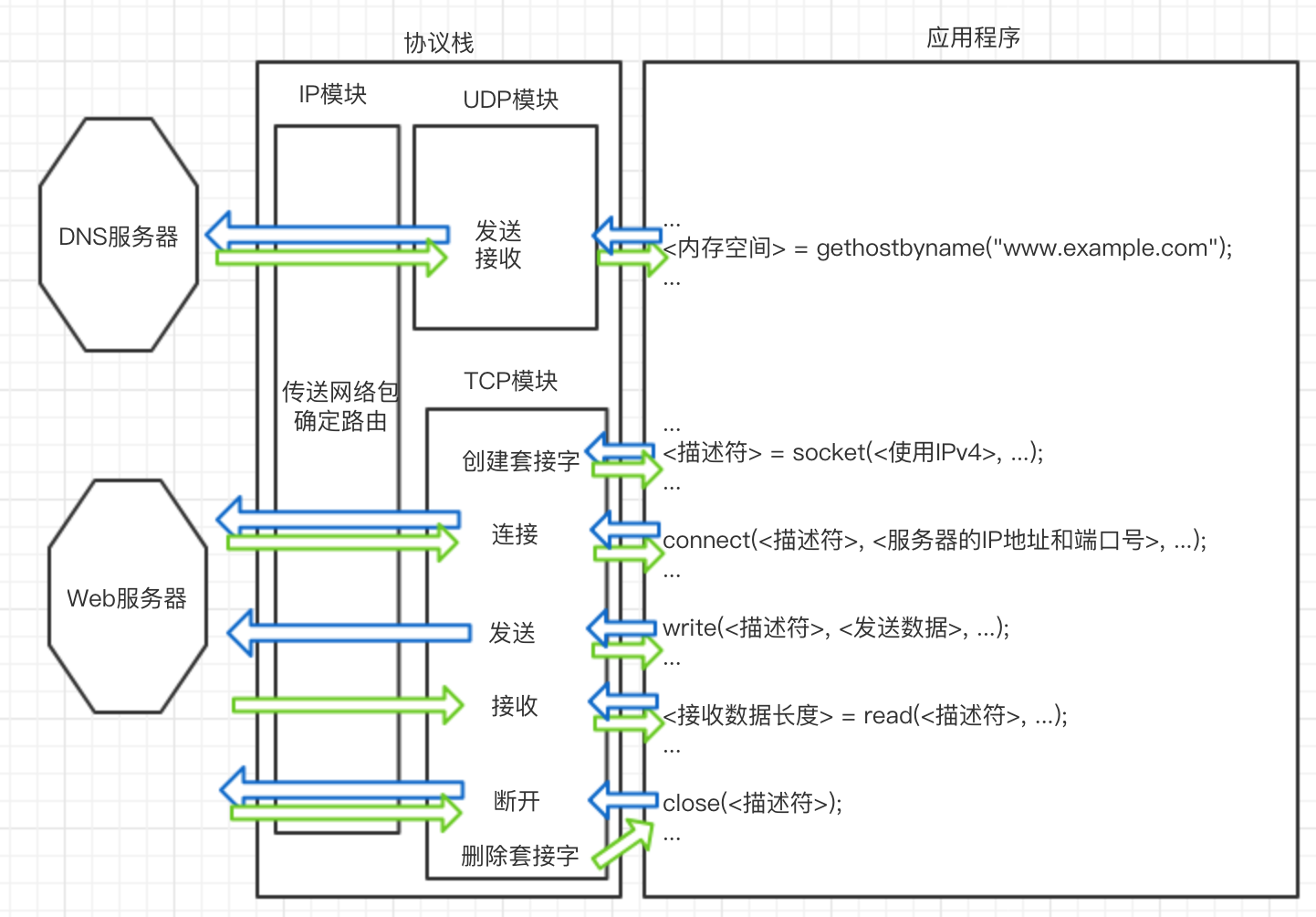
Once the ip address is known, the browser can delegate the operating system’s protocol stack to send a message to the target ip. The browser will call the program components in the Socket library in the order specified.
- create socket
<descriptor> = socket(<using IPv4>, ...) ; - connect the pipe to the socket on the server side
connect(<descriptor>, <server's IP address and port number>, ...) ; - send and receive data
write(<descriptor>, <send data>, ...) ;`= read( , ...) ;` - Disconnect the pipe and delete the socket
close(<descriptor>) ;
So how exactly does the protocol stack work? Let’s keep exploring.
2 The stack sends a message over TCP.
TCP is used to send and receive data for general applications such as browsers and emails. UDP for sending and receiving short control data such as DNS queries.
2.1 Creating Sockets
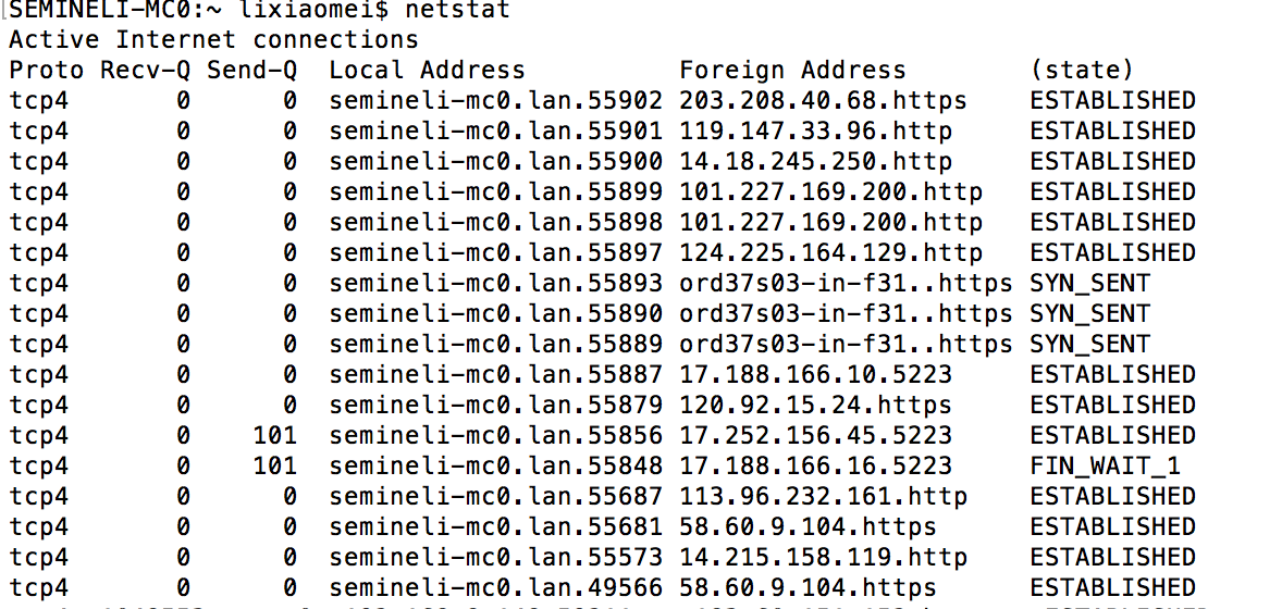
The entity of a socket is the communication control information. Inside the protocol stack there is a memory space used to store control information, such as the IP address of the communication object, the port number, the status of the communication operation in progress, and so on. This memory space is the entity of the socket. You can use the netstat command to display the contents of a socket, as follows
The process of creating a socket is:
- the protocol stack receives a request from the application to create a socket
- Memory space is allocated to hold the socket.
- initial state control information is written to the memory space
- the descriptor representing the socket is returned to the application.
And the remote server creates sockets at system startup and waits for clients to connect.
2.2 Connections
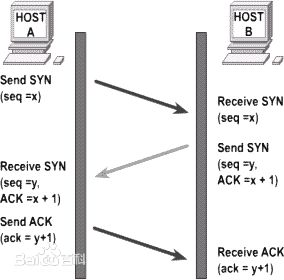
Because there is only initial state control information in the socket, the browser needs to inform the protocol stack of the server’s IP address and port number and other control information when it calls connect of the socket library, and the client in turn informs the server of our client’s IP address and port number and other information (TCP headers). This exchange of control information establishes the connection. This process is also known as the “three handshakes” of TCP.
This is also known as the “three handshakes” of TCP. three handshakes
The process is specifically this:
(1) The client creates the TCP header
The client creates a header (TCP header) that contains control information, among which are the port numbers of the client and the server. With the port numbers, the client’s socket knows which of the server’s sockets to connect to. And it sets the SYN bit of the control bit field in the header to 1 to indicate the connection.
The following are the main TCP header fields, the specific settings of the fields will be mentioned in the following sections.
| Field Name | Meaning |
|---|---|
| Sender port number | Port number of the program sending the network packet |
| Receiver Port Number | Port number of the program that is receiving the network packet. |
| Sequence Number | The sequential number of the sent data, the sender tells the receiver that this is the first byte of all the sent data. |
| ACK Number | The sequential number of the received data that tells the receiver that the sender has received the first byte of all sent data |
| Control Bits | Each bit in this field is: URG, ACK (Accepted Valid, usually means data has been received), PSH, RST (Exceptional Interrupt), SYN (Connect), FIN (Disconnect), respectively |
| … | … |
(2) The client passes the information to the IP module and entrusts it to send it, and when it reaches the server, the server returns the response.
After arriving at the server through the network, the server’s IP module passes the data to the TCP module, which finds the corresponding socket based on the information in the header (port number), and the socket writes the relevant information. Then, the server’s TCP module returns the response, setting the port number and SYN bits in the TCP header as the client did in step 1, in addition to setting the ACK number and setting the ACK control bit to 1 to indicate that the network packet has been received.
(3) the client receives the network packet in response.
The network packet reaches the TCP module via the IP module and confirms that the connection to the server was successful with the TCP header information (whether the control bit SYN bit is 1). If successful, it writes the server’s IP address, port number, etc. in the socket and changes the state to established. Then the client __ sets the ACK number and specializes the ACK ratio to 1__, which is returned to the server to indicate that the network packet has been received. After the server receives this network packet, the connection operation is complete.
2.3 Sending and receiving data
When the control flow returns from connect to the application, the next step is to call the socket library’s write to give the data to be sent to the protocol stack, which receives the data and performs the send operation.
(1) Timing of sending.
The protocol stack does not send out data as soon as it receives it, but instead stores it in an internal send buffer until a certain amount is available. This value is determined based on two factors: the length of data each network packet can hold; and how often the application sends data. This value is set differently on different operating systems. If length is prioritized, efficiency is high and latency is long; if time is prioritized, efficiency is reduced and latency is decreased. In addition, the application can specify options, for example, browsers typically use the option to send directly without waiting to fill the buffer.
(2) Splitting larger data
When an HTTP request message is very long (such as a POST request to submit form data) and exceeds the MSS length, the data in the send buffer is split by the MSS length, TCP headers are added, and put into a separate network packet.
MTU: the maximum length of a network packet, usually 1500 bytes in Ethernet. MSS: Maximum length of a packet, theoretically MTU minus the header length
(3) Use the ACK number to confirm receipt of network packets
The principle of acknowledgement works like this: During the first handshake to establish a connection, the value of the serial number field is set (the initial value of the serial number) while setting SYN to 1.
When TCP splits the data, it calculates that this piece of data corresponds to the first byte of all data (counting from the initial value) and writes this number to the Serial Number field in the TCP header. When the receiver receives a network packet, it calculates the length of the data (Data Length = Network Packet Length - Header Length) and returns it to the sender by writing the total length of the data received so far into the ACK number field of the TCP header.
This allows the receiver to check in this way: last time it received the nth byte, and this time, if it receives the packet with serial number n+1, it has not missed it. The sender can also confirm that the receiver has received n data so far, and should send the packet with serial number n+1 this time.
In addition, the sent packets are saved in the send buffer, and if the other party does not return the corresponding ACK number, these packets will be resent.
(4) Receiving HTTP response messages
After sending a request message, the browser calls read to delegate the protocol stack to get the response message. Like mentioned above on the receiving side, the protocol stack checks if the data block is missing after receiving all the data, if not it returns the ACK number and concatenates the data blocks in order and finally hands them over to the application.
2.4 Disconnection
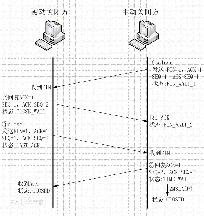
After sending and receiving data, both the server and the client can first initiate a disconnection, here to disconnect the pipe from the server and delete the socket as an example. The process of disconnecting is also known as TCP’s “four handshakes”. The process of disconnection is also known as TCP’s “four handshakes”. four waves
- The server application calls the socket library’s
closeprogram, and the stack generates a TCP header containing the disconnect message, i.e., the __FIN bit in the control bit is set to 1, and the IP module is delegated the task of sending the data to the client. At the same time, the server’s socket records the disconnect operation (change of state, etc.). - When the client receives a TCP header with a FIN of 1, the client’s stack sets the socket’s state to disconnect and returns an ACK number to tell the server that it has received it. After that, it waits for the application program to get the data.
- The application calls
readto read the data as described above inReceiving HTTP Response Messages. If the stack has received all the data, it can read it right away; otherwise, it continues to wait for the stack. 4. - Finally, the application calls
closeto end the operation. At this point the stack generates a packet with a FIN bit of 1, just like the server in step 1, and sends it through the IP module. The server receives it and returns the ACK number. This concludes the operation.
After the communication with the server is finished, the client waits for some time to delete the socket.
3 Packet sending and receiving operations for IP and Ethernet
Continue with a cup of tea.
Next we explore how IP and Ethernet perform packet sending and receiving operations.
We have often referred to the IP module of the protocol stack in the sections above, what exactly does the IP module do?The IP module is responsible for adding two headers to the packet:
- IP Header: Header for IP, includes IP address
- MAC header: header for Ethernet, includes MAC address
3.1 Generating IP Headers
The main fields are as follows
| Field Name | Meaning |
|---|---|
| Flag | Indicates whether fragmentation is allowed, and whether the current packet is a fragmented packet or not |
| Protocol Number | Indicates the type of protocol, e.g. TCP: 06, UDP: 11. |
| Sender IP Address | IP address of the sender of the packet. |
| Receiver IP Address | IP address of the receiver of the packet. |
| … | … |
Among them, the receiver IP address is what the TCP module informs, while the sender IP address needs to be determined by determining the NIC used for sending and filling in the IP address of that NIC. How to determine which NIC to use for sending, the IP module will determine which NIC to give the packet to based on the routing table. We can display the routing table in route print.
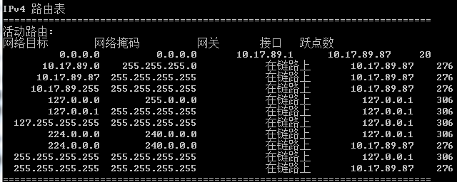
First, the destination ip in the socket is compared to the Network Destination to find the matching row; then the row is viewed, the Gateway, which is the ip address of the next router (nearest network forwarding device) to be forwarded to, and the Interface, which is the ip address of the NIC used. This way, we know which NIC to use to send the packet, i.e. the sender ip address field in the IP header.
3.2 Generating MAC Headers
Ethernet differs from TCP/IP in the way it determines the destination of a network packet, and requires knowledge of the MAC address in order to send the packet to its destination in Ethernet. Therefore, a MAC header is also required. Main fields of MAC header
| Field Name | Meaning |
|---|---|
| Receiver MAC Address | MAC address of the receiver of the network packet |
| Sender MAC Address | MAC address of the sender of the network packet |
| Ethernet Type | The type of protocol used, e.g. 0800: IP protocol, 0806 ARP protocol, etc. |
We just said that by checking the routing table we can know the ip address of the next router to be forwarded to and the ip address of the NIC used, and the MAC address we get from these two ip address queries is the MAC address of the receiver and the MAC address of the sender. Here we need to use ARP. Specifically, in Ethernet, we can send packets to all devices in the same subnet by broadcasting. ARP is to use broadcasting to ask all the devices: “Whose IP address xxx.xxx.xxx.xxx is this? Please give me your MAC address.” Then a device will reply, “This IP address is mine, and my MAC address is XX-XX-XX-XX-XX-XX.” so that we can get the corresponding MAC address.
3.3 The NIC converts packets into electrical/optical signals and sends them out
Once the network packet is received by the network card, it converts the network packet generated by the IP module into an electrical or optical signal so that it is transmitted over the network cable. We won’t go into details here.
3.4 Router packet forwarding operations
After the packet arrives at the router, the router will once again determine the ip address of the next router to which it is to be forwarded according to the routing table, rewrite the receiver’s MAC address in the MAC header, and then forward it to the next router. This process is repeated over and over again, and eventually the network packet is delivered to its destination.
Before forwarding, when the length of the packet is greater than the output port’s MTU (the maximum length of data that can be transmitted in a packet) and the flag field in the IP header indicates that it can be fragmented, the router will use the fragmentation feature to split the large network packet and update the IP header. If the packet is too large and slicing is not allowed, the router discards the packet and notifies the other party via an ICMP message.
4 The request reaches the server and the response is returned to the browser
Before reaching the server, it is possible that the network packet may also pass through a firewall, or read data directly from the cache server as it passes through the cache server, which will not be discussed in detail here.
4.1 Receive operations of the server
(1) After arriving at the server, the server’s NIC converts the received signal into digital information, verifies the signal for distortion, and checks the receiver’s MAC address in the MAC header of the packet. After the check is completed, the NIC will notify the CPU of the arrival of the packet through an interrupt, and then the NIC driver will hand the packet over to the appropriate protocol stack according to the protocol type in the MAC header.
(2) The protocol stack IP module will first check the IP header to see if the packet is fragmented. If it is a fragmented packet, the packet is temporarily stored in memory and then restored to the original packet when all the fragmented packets have arrived. Then it checks the protocol number field in the IP header and hands the packet to the appropriate module.
(3) The TCP module checks the TCP header of the packet and then finds the corresponding socket based on the sender IP, sender port number, receiver IP and receiver port number. If it can find the corresponding socket then it returns the ACK number (the second handshake) and finally establishes the connection (completing the three handshakes). After the connection is established, the TCP module will check the serial number of the TCP header, and if it is normal, it will put the packet into the buffer, and finally restore it to the original packet.
As we mentioned in 3.1, the server creates sockets at startup to wait for connections. Each time a new client initiates a connection (the first handshake), the server starts receiving connection operations. The protocol stack makes a copy of the socket waiting for a connection and writes control information to this new socket. This socket has the same port number as the socket waiting to connect, so other information is needed to make the difference.
(4) After TCP has completed all data receiving operations, the control flow is transferred to the server program to process the received data.
(5) When the data sending and receiving is complete, the disconnect operation is performed.
4.2 Browser accepts response message
After the response message sent by the server reaches the client, it passes through the network card, the protocol stack, and finally reaches the browser.
Next, the browser will be based on the http header Content-Type field, file extensions, etc. to determine the type of data, and then display the data on it. The process of displaying data of different types is not the same, so we won’t discuss it here.
The browser displays the content of the page successfully! User access is complete!
Reference
- How the Network is Connected